Paratable 20100608

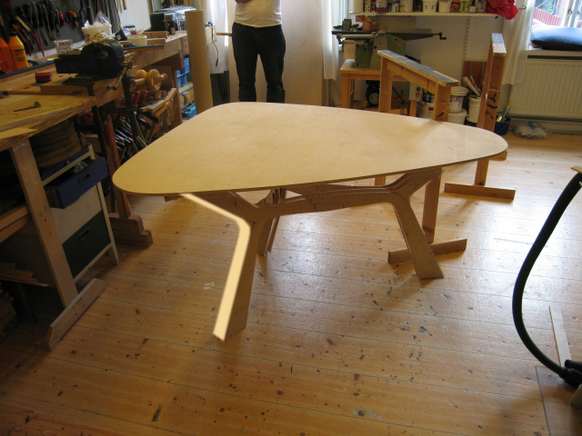
Update on the work with the full scale physical prototype done. There is tendency for rotation of the tabletop that comes with material performance and the structural solution that needs to be overcome. The aim is to find a solution for this very soon, in order to move on to production issues. We are also considering to enter in the Asahikawa international furniture design competition, at the first stage this only requires visualizations.
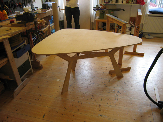
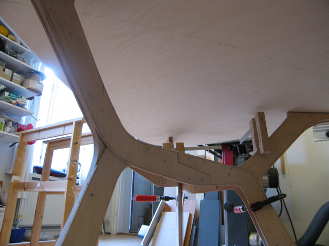
paratable physical prototype
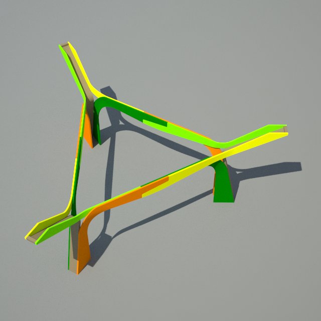
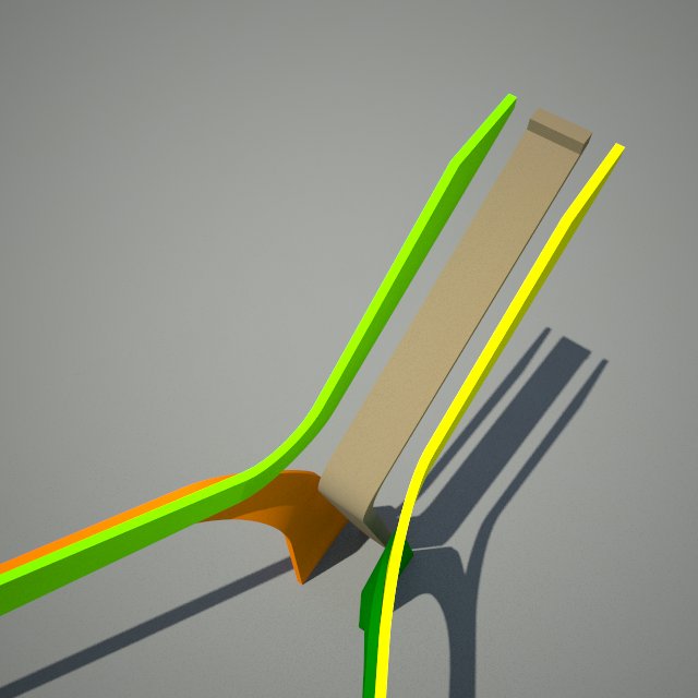
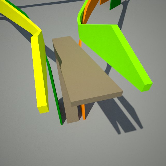
structure detail
structure detail
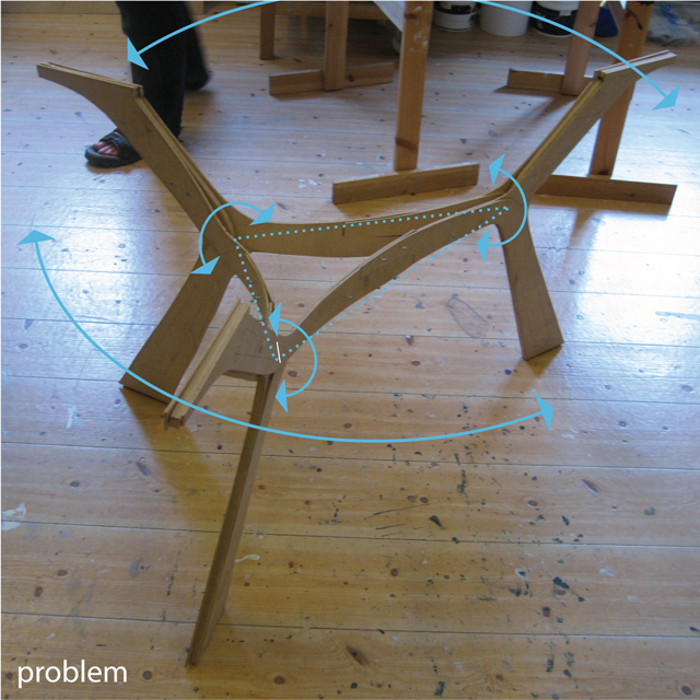
rotational problems: overall rotation of tabletop potentially due to rotation of the joinins points between upper and lower leg and horizontal members
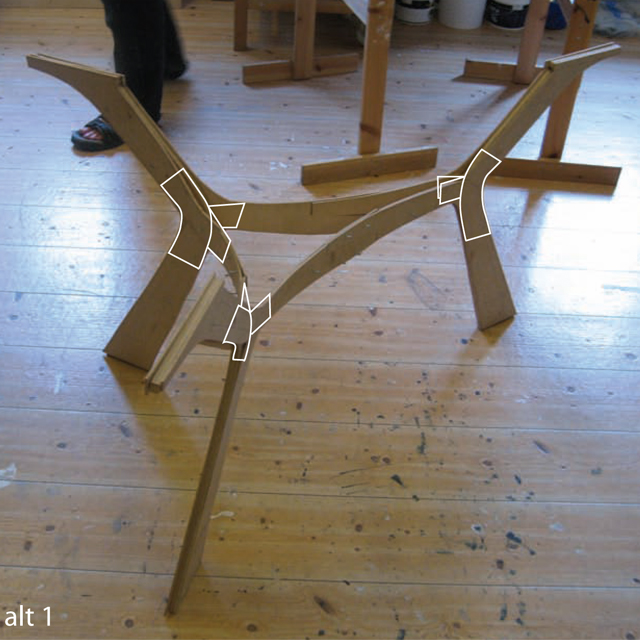
alternate solution 1
alternate solution 1: fixing the joint
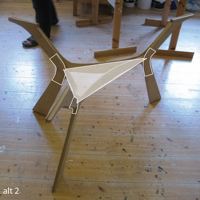
alternate solution 2
alternate solution 2: fixing joint to triangle
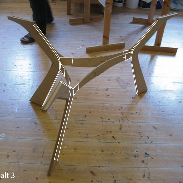
alternate solution 3
alternate solution 3: inside band fixing joints
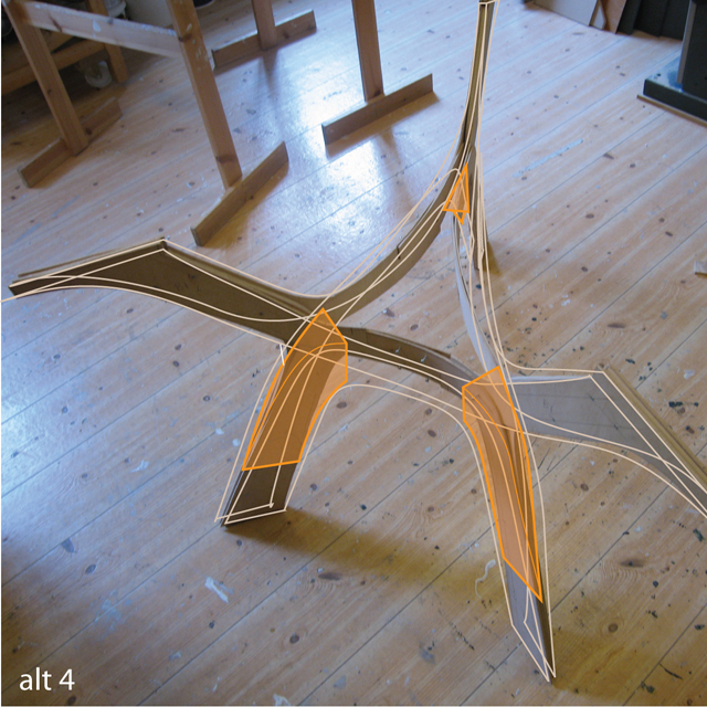
alternate solution 4: widening the connection by inserting wedges that makes the point of intersection between top and bottom part of leg and horizontal triangle "wider", thereby adding structure that limits horizontal rotation and torque.
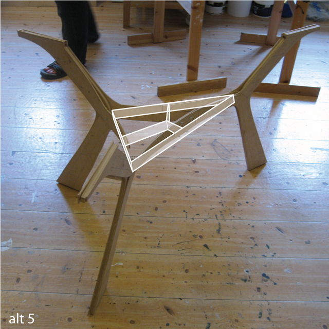
alternate solution 5: "deep" triangular inside structure
alternate solution 5: "deep" triangular inside structure that stops horizontal members from torquing. Possibly the "cross" is enough to accomplish the same.
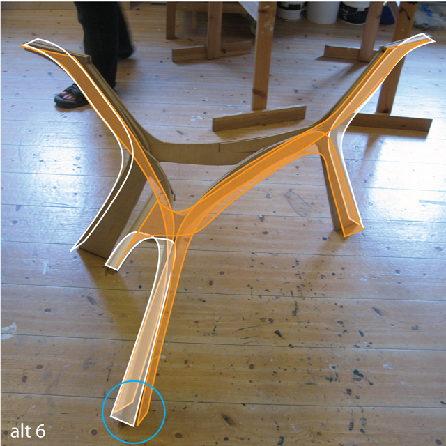
alternate solution 6: turning the vertical leg 90 degrees, which should make it stronger in the "rotational direction". When connected to the horizontal members, a box is created which further improves this
alternate solution 6: turning the vertical leg 90 degrees, which should make it stronger in the "rotational direction". When connected to the horizontal members, a box is created which further improves this. Image shows only a few of the vertical members, but the blue circle indicates how they are fixed together.
alternate solution 6 collage: rough photoshop on what alternative 6 would look like
alternate solution 6 render 1: new assembly
alternate solution 6 render 1: detail before assembly

Leave a Reply

Your email address will not be published. Required fields are marked *